Controls

Controls & Coin

The Jammafier has a very rapid update frequency (around 350Hz) which makes it practically lag-free.

Cabinet signals on Jammafier

JVS IO-board / CabinetJammafier Game ConnectorJammafier JST-XH 
TestTest 
Service Player 1Service 
Service Player 2Service 
Credit increase, slot 1Coin A 
Credit increase, slot 2**Coin B 
Sticks, button 1 to 3Sticks, button 1 to 3 
Button 4 and 5Button 4 and 5Button 4 and 5
Button 6 Button 6

**) Not all IO boards/cabinets have support for 2 coin slots

Kick harness – buttons 4,5 & 6

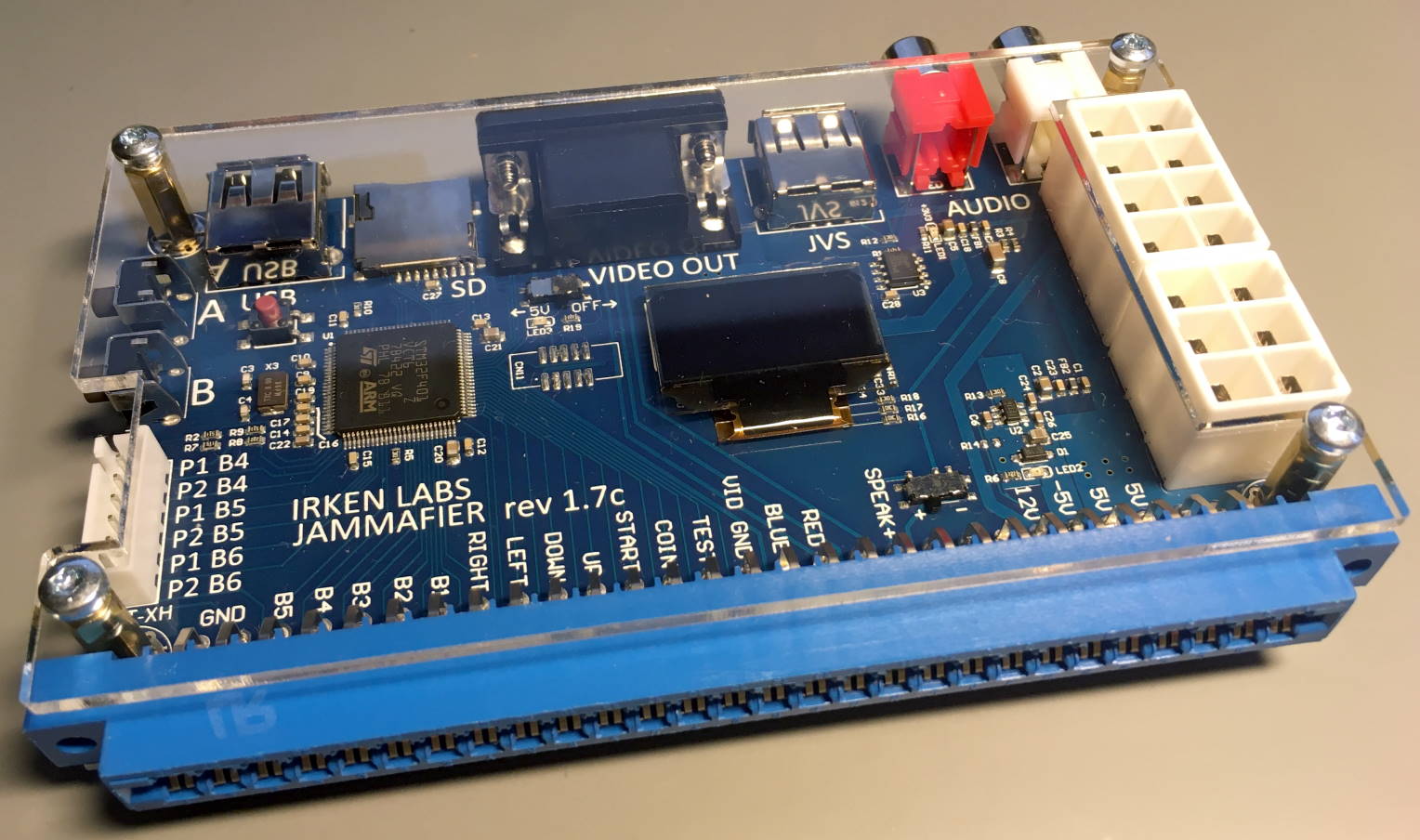
For games that use an additional connector for buttons, they are available on the JST-XH 6 pin header.  The pin-out is clearly marked on the PCB, and is the same used by RGB on his HAS super-gun.

Coincidentally (not really ☺), JST-XH is used in a lot of RC hobby products, so it’s easy to find something that gets you half-way there.  Just search ebay for “JST-XH 5S”, or “1P5S” and you should find many alternatives.  A length of 30cm should be plenty, and I recommend getting one where the individual leads have different colors. 

JST-XH pinFunction
1Player 1 Button 4
2Player 2 Button 4
3Player 1 Button 5
4Player 2 Button 5
5Player 1 Button 6
6Player 2 Button 6

Selectable output for button 4&5

Some games are programmed in a way that buttons 4&5 must be via a kick connector, but will get confused if they at the same time receive input for buttons 4&5 via the Jamma edge.  This is pretty rare, but you may run into it.  By default buttons 4&5 is output BOTH to Jamma and kick – but this can be selected via the menu with 2 options:

  • Buttons 4/5 on both Jamma and JST-XH – default
  • Buttons 4/5 on JST-XH only

Namco issues

JVS does not have the notion of coin input, but has a more advanced system where the IO board keeps track of available credit.  For this to translate into Jamma, a coin event has to be emulated by pulsing the coin input on the Jamma edge.  The Namco adapter does this in a way that some games don’t understand/like – most notably the Cave CV-1000 series of PCB’s.

Video

Video output

On revisions prior to 2.0, the Jammafier does not touch the video at all.

Revision 2.0 has two modes, JAMMA which is untouched like earlier versions and Tri-Sync mode (default). In Tri-Sync mode RGB is attenuated and re-amplified, while sync either split into H/V, or processed into regenerated CSYNC.

Regenerated CSYNC will fix issues some games have with Sanwa PFX monitors, while Toshiba PF monitors seem to prefer H/V sync.

PinJamma settingTri-Sync setting
1JAMMA Red75-ohm Red
2JAMMA Green75-ohm Green
3JAMMA Blue75-ohm Blue
4n/cn/c
5GNDGND
6GNDGND
7GNDGND
8GNDGND
9Rev 2.0 n/c
Earlier optional 5V
n/c
10GNDGND
11n/cn/c
12n/cn/c
13JAMMA CSYNCHSYNC or CSYNC
14n/cVSYNC or n/c
15n/cn/c

Some notes on Jamma video for the technically inclined

Adding 220 Ohm series resistors on RGB lines

A few people have reported success in bringing the video levels down to 0-1VPP levels by adding 220 Ohm resistors in series with the RGB signals, which is required by some tri-sync CRT monitors.

If this signal is fed into a monitor with 75 Ohm termination resistors, it effectively results in a voltage divider that divides the signal by approximately 4 – IF the output impedance of the game is very low (strong).

There are 2 issues with this approach:

  • The game is loaded with 295 Ohm, which is out of spec
  • It does not take the output impedance of the game into account.

The resulting video levels will be highly dependent on the games output impedance, which unfortunately varies a lot.

Namco issues 

The Namco adapter uses active electronics to change the impedance of the signal – and in the process introduces a noticeable distortion/softening of the image.

TODO: Check RGB output levels when loaded 75Ohm.

Riverservice RS issues

The RS use 75Ohm termination on RGB.  This is not great for a couple of reasons:

  • Jamma games do not have an impedance of 75Ohm, meaning the load put on them is too high and may cause failure
  • If this signal is fed to a scaler/monitor that also terminates the video with 75Ohm – the resulting load will be 37.5Ohm, about 30 times higher than what the games are designed for (1kOhm).

Very few games actually have 1kOhm output impedance, somewhere in the hundreds is more normal – regardless, the 75Ohm termination serve no good purpose (that I know of), and put a load on the RGB outputs that is way out of spec.

Konami

The Konami does a very good job of actively attenuating and re-amplifying the signal to 75Ohm with levels within 0-1VPP, it also does this without loading the game out of spec.

Jammafier FAQ

FAQ

I’m getting “No IO, retry x”

Make sure your JVS cable is plugged into the connector marked ‘JVS’.  JVS uses the same connector as USB, which is a major source of confusion, especially on boards like the Jammafier that has both USB and JVS.

I’m getting “Unknown IO”

This is because you are (one of) the first to use the Jammafier with that particular IO board.  Please get in touch so the firmware can be updated and correctly identify it.  

What is the USB port used for?

The USB port can be used to power 5V devices from the cabinet power supply.

Can the Jammafier be used in LCD cabinets like the Taito Vewlix?

Yes – but video will have to go through an upscaler.

I want to use a video processor/up-scaler, but it only has connector X for input, what do I do?

Sorry about connector X, it can be a real PITA.  Your best bet is to find a plain connector X to VGA cable, or make your own.

If you make your own, you can find nice breakout’s on ebay by searching for “VGA MALE BREAKOUT SHELL”.

Does it support racing/gun games?

The Jammafier is digital only, i.e. buttons and sticks via the Jamma connector.  

Why is it called Jammafier?

For lack of a better name – it was originally named JVS2JAMMA, but some people confused this with an IO board for Jamma cabinets.


Firmware update

Firmware update

The firmware can be updated using a standard Micro SD card. The card must be formatted with a FAT file system.  It is not possible to ‘brick’ or damage the unit during firmware update, if you experience an error – simply try again.

Download zip file below, and extract files to root of sd card.

Update procedure

  • Power off system
  • Insert SD card into Jammafier
  • Press and hold both A and B button
  • Power on system
  • Follow instructions on screen


Firmware, works on all revisions

2023-09-10 – Fixed/Improvements in this release

  • Major JVS update
  • Internal cleanups and updates

2022-07-28 – Fixes/Improvements in this release

  • Shipped with rev 2.0 boards
  • Internal code cleanup
  • Compatible with earlier revisions

2020-04-22– Fixes/Improvements in this release – shipped with Rev 1.7 boards

  • Optimized start sequence
  • Shows voltages when no IO is connected/detected, including 3.3V rail
  • Internal cleanups and updates

2020-04-12– Fixes/Improvements in this release

  • Screen saver
  • Correctly identifies G-Balance IO board 
  • Correctly identifies Cyber Lead 2.02 IO board
  • Fix bug affecting cabinets with Taito RF-ID card readers
  • 2 new MVS remaps to mimic NeoGeo pads
  • Ability to access MVS Universal Bios menu/test by holding button A or B on start
  • Remap type ‘tate’ for playing vertical games in horizontal cabinet
  • Shows firmware version and voltages, including 3.3V, if there is a JVS issue

2019-02-16– Fixes/Improvements in this release

  • Correctly identify Konami Windy 2 IO board
  • Fix debug to file

2018-12-02 – Fixes/Improvements in this release

  • Increase duration of coin pulse and make it configurable via .ini file

2018-09-17 – Fixes/Improvements in this release

  • Correctly identifies Namco Noir IO board
  • Correctly identifies Egret 3 IO board
  • Fix Vewlix IO typo
  • Menu system with options and config save to micro-sd card
    • Neo Geo remap
    • Option to have buttons 4&5 on JST-XH only
    • JVS Input test
    • Display PCB version and serial number

2018-08-20t2 – Increase packet reception timeout

2018-08-20t1 – Add debug 3.3V reading, adjust startup timers

Operation

Operation

First time use

  1. Turn cabinet OFF
  2. Connect JVS and both power cables to Jammafier, do not connect game PCB
  3. Turn cabinet ON, the LED on the Jammafier should immediately turn on
  4. Verify on OLED that IO board is found.
  5. Verify supply voltages on OLED.
  6. Turn cabinet OFF

Use with game

  1. Turn cabinet OFF
  2. Make sure cables from cabinet is connected to Jammafier:
    • Both JVS power cables
    • JVS ‘usb’ cable
    • Audio cables
    • VGA cable*
  3. Gently connect Jammafier to Jamma game board – the OLED display should face upwards
  4. Turn cabinet ON

Warning! Using the Jammafier in dual-power setups, i.e. game is not powered directly from the Jammafier is not supported or recommended. 

Screen Saver

The OLED display will shut down after 5 minutes of no user interaction.  It will power-up on immediately on user input, or if JVS state changes.

NeoGeo MVS UniverseBios function

http://unibios.free.fr/howitworks.html

If you have this bios in your NeoGeo, you can start the Jammafier with button A pressed to access the Universe Bios Menu, or button B to access test mode.

On release, the Jammafier will continue it’s startup function and initialize JVS.

Menu system

B button toggles between the different options/screens.  Button A changes/activates option.

JVS Input test

This displays active button switches on your JVS cab – useful for troubleshooting

Button 4&5 Option

Toggles between button 4&5 being active on edge connector and kick, or just kick.  This is needed for some CPS2 games.

Remap Input

You can remap the cabinets input, for normal use leave the setting at the default ‘none’. 

The available presets are:

  • None – no remapping
  • MVS 
  • MVS KOF 
  • MVS Pad
  • Tate – ‘useful’ when you have vertical games in a cab with horizontal monitor

Information

Shows the firmware version, PCB version and serial number of the Jammafier

Save config

Saves configuration to micro-sd card.

power delivery

Power delivery

JVS and JAMMA have slightly different approaches when it comes to power delivery:

RailJVSJAMMAJammafier
-5Vn/aYES – 2 wiresGenerated on-board
3.3VYES – 2 wires n/aUsed by Jammafier 
5VYES – 2 wiresYES – 4 wiresPassive  delivery, monitored
12VYES – 1 wireYES – 2 wiresPassive delivery, monitored

The Jammafier takes 5V and 12V from your cabinet and delivers it passively.  In addition, it has an on-board DC-DC inverter that generates the -5V needed for some games.  

The Jammafier itself only consumes 3.3V, and will not interfere with 5V delivery.

You need to connect both connectors for the Jammafier to operate properly, and ensure good power delivery to your game.

Warning 

DO NOT connect a Jamma game to the Jammafier before verifying your cabinet delivers correct power.  You can do this by connecting the Jammafier to your cabinet with no game, and verify the voltages on the on-screen voltmeter. 

If the voltages shown on the Jammafier varies a lot between games, it is an indication that the power cables in your cabinet are not thick enough.  With proper cabling, it should not be necessary to adjust the voltage on your PSU when changing games.

Details on power for the technically inclined

To ensure good power to your game, there are basically 2 things that needs to be in place:

  • A good power supply that can supply stable voltage for power hungry games (high current)
  • Minimal resistance between supply and game

JVS Power

These are the JST-VL connectors and pin-outs specified in the JVS Standard, image is looking at the game.  Although it has a lot of wires, only 5V is of interest when it comes to Jamma games.  Naomi Unversal cabinets use 18AWG wires, so effectively 1x15AWG is available for power delivery. 

What is voltage drop?

If you measure the voltage coming out of your power supply, you may get a different reading than if you measure the actual game.  This is called voltage drop, is caused by the wires used, and the formula is basically just Ohm’s law:

Vdrop = IR,

where I is the current your game use and R is resistance of the wires between game and power supply, including return GND wires.

You can’t do much about the current consumption of the game, so the only variable left is the resistance of the wires.  Resistance in wires is affected by:

  • Material
  • Width
  • Length

Thin long wires have higher resistance than short thick ones – and in general you want to try to have them as short and thick as possible.  Using wires in parallel to decrease resistance works well, and is used by both old Jamma and JVS.  For every doubling of wires, subtract 3 from the AWG number:

  • 2xAWG24 is the same as 1xAWG21. 
  • 4xAWG24 is the same as 1xAWG18 (2xAWG24=1xAWG21, 2xAWG21=1xAWG18)
  • 2xAWG18 is the same as 1xAWG15. 

Incidentally, (not really☺), AWG15 has half the resistance of AWG18.  This leads to a couple of rule-of-thumbs:

  • 2 x current (power usage) = 2 x voltage drop
  • Half the resistance = half the voltage drop

This is a real issue – the game Salamander uses 4.1A, while Cave SH-1 only uses 0.5A.  In the same cabinet, the Salamander game will have EIGHT times the voltage drop of the Cave game.

Namco issues

The Namco JVS2JAMMA has 3 main issues when it comes to power delivery.

  • Jamma harness cabling
  • PCB layout
  • PCB current draw

The wire harness on the Namco uses 4*24AWG cables for 5V, which equals a single 18AWG wire. Although it is pretty short, combined with the PCB layout and the fact that the PCB itself uses 0.5A, it all adds up to it being problematic with power hungry games.

Konami issues

While the Konami does a lot of things right, it was one major fault:

  • Single power connector

This effectively means only one wire is used for 5V, and in the case of Naomi Universal – it will be a single 18AWG.  The Konami does not generate -5V, but it has a header that is routed to the Jamma connector – so it is possible to feed it via a “Negatron” or similar device.

Riverservice/RS issues

No -5V, and no header – soldering required if you need it.

Introduction

Introduction

The Jammafier is a device that enables you to play older Jamma PCB’s in a JVS only cabinet, like the Sega Naomi Universal.  It handles controls, power and audio – but does not touch the video signals.  The intention is to address a few shortcomings of existing solutions, both technically and when it comes to availability – I hope you like it 🙂

Features

  • Rapid JVS updates for minimal lag
  • Optimized layout for low voltage-drop
  • -5V generation
  • OLED display for diagnostics, including precision volt-meter for 5V and 12V
  • Attenuated audio via two RCA connectors for easy use with cabinet amplifier.
  • Raw video /sync, or 75-ohm video and processed sync via VGA connector*
  • Buttons 1-5 on Jamma connector
  • Buttons 4-6 on auxilary ‘kick’ connector
  • MVS remap – ‘Neo Geo layout’ on 6 button panels
  • Easy firmware update via micro-sd

*)  VGA connector chosen for convenience and availability of cables. The Jammafier does not touch the video signals generated by the Jamma PCB, and you will most likely need an additional device to modify the video signals for use with a modern monitor. Processed video/sync only available on revision 2.0 and newer.

Disclaimer/Warning

Short version: I shall not be held responsible for destroying your PCB’s or if your house catches fire – check that your game and cabinet power supply is working correctly.  Your cabinet power supply is capable of delivering enough current to do serious damage to everything it powers.

Each time you use the Jammafier, you risk catastrophic failure of your cabinet, Jammafier or game.  You can substantially reduce this risk by:

  1. Assuring that every component is working correctly 
  2. Assuring that every component is connected correctly
  3. Obtain instructions on how each component is operating
  4. Never leave a powered system unattended

However, electronics sometimes fail to operate properly – even when properly assembled and operated – so you risk catastrophic failure or fire each time you use the Jammafier.