
Introduction
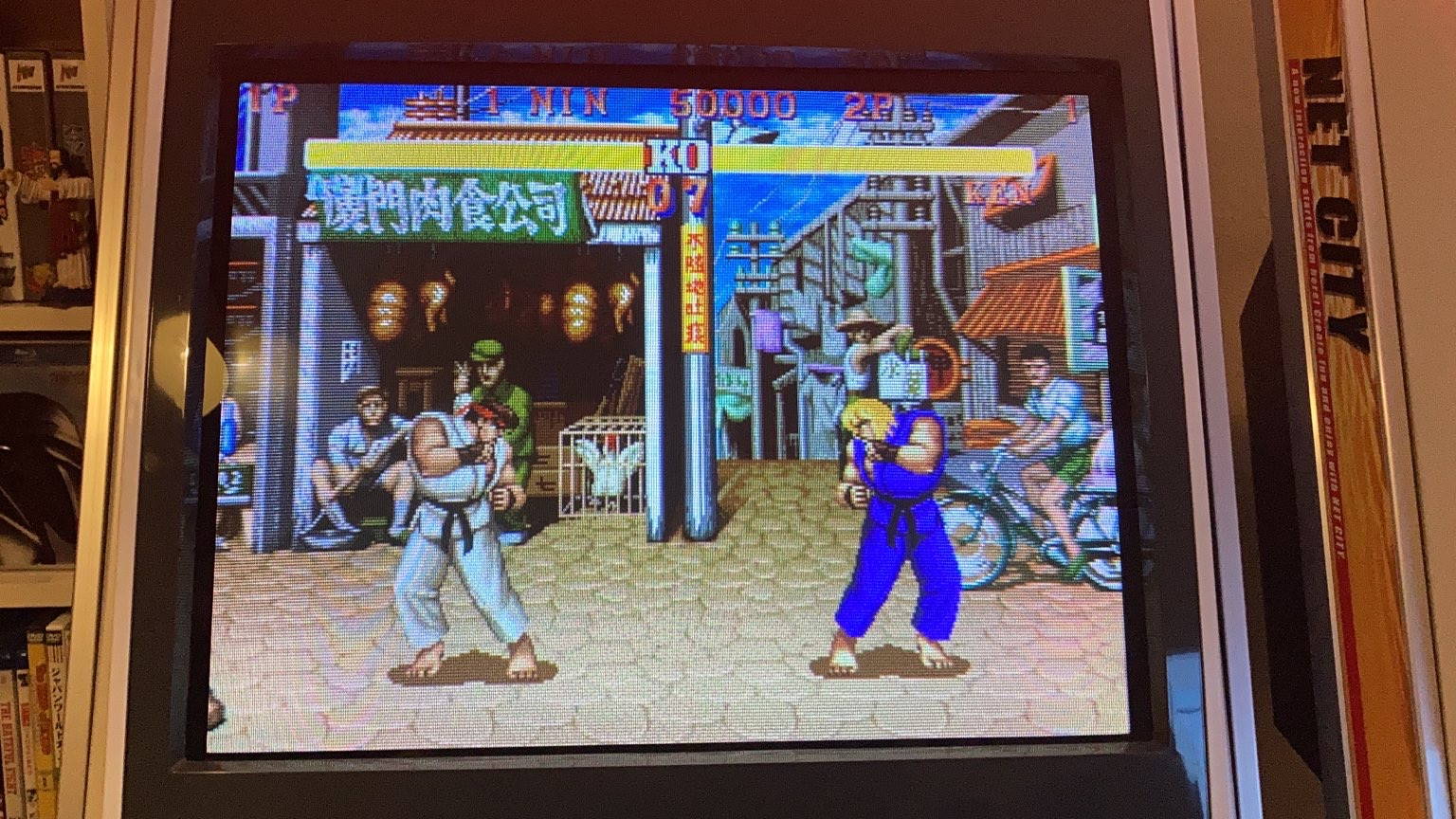
This page is about getting MiSTer running in your 31KHz/Tri-Sync JVS cabinet as quickly as possible.
Hardware
- DE10-Nano kit
- SDRAM module
- micro SD card, I use a 16GB card that has 14GB unused
- HDMI to VGA dongle, with analog audio out.
- JVS-PAC 2 🙂
- USB OTG adapter
- 3.5mm to RCA adapter for Audio
In other words, the only MiSTer specific hardware you need is the SDRAM module.
Part 1 – Installing MiSTer
Step 1 – Preparing the SD card
First you need to install “Mr. Fusion – Universal MiSTer installation image” on an SD card, https://github.com/MiSTer-devel/mr-fusion. You do this from a normal computer.
Step 2 – Power up and update MiSTer
For the initial setup, it’s probably best to do it on a desk with a keyboard, an ethernet cable and a normal HDMI monitor.
Boot up MiSTer, press F12, navigate to “Scripts”, and choose “update”, let it do it’s thing.
Step 3 – Making MiSTer useful
How MiSTer organizes cores, roms, launching files etc is a bit of a moving target and can be confusing and frustrating to set up from scratch. Luckily, there is a script that does everything for you:
https://github.com/theypsilon/Update_All_MiSTer
Run this script, and it should take care of making your MiSTer useful.
Part 2 – Getting your MiSTer cab ready
Step 1 – Configure video
Before running the DE10-Nano in your cab, you will need to do a couple of changes. Boot up MiSTer, press F12, navigate to “ini settings” and make the following changes:
video_mode=640×480 60Hz
vsync_adjust=low_lag
vscale_mode=Use integer scale only
direct_video=on
video_info=10 seconds
For 31kHz only cabinets, also set
forced_scandoubler=on
The video mode setting above is just for the menu when booting, games will run at native resolutions, or line-doubled for 31kHz only cabinets.
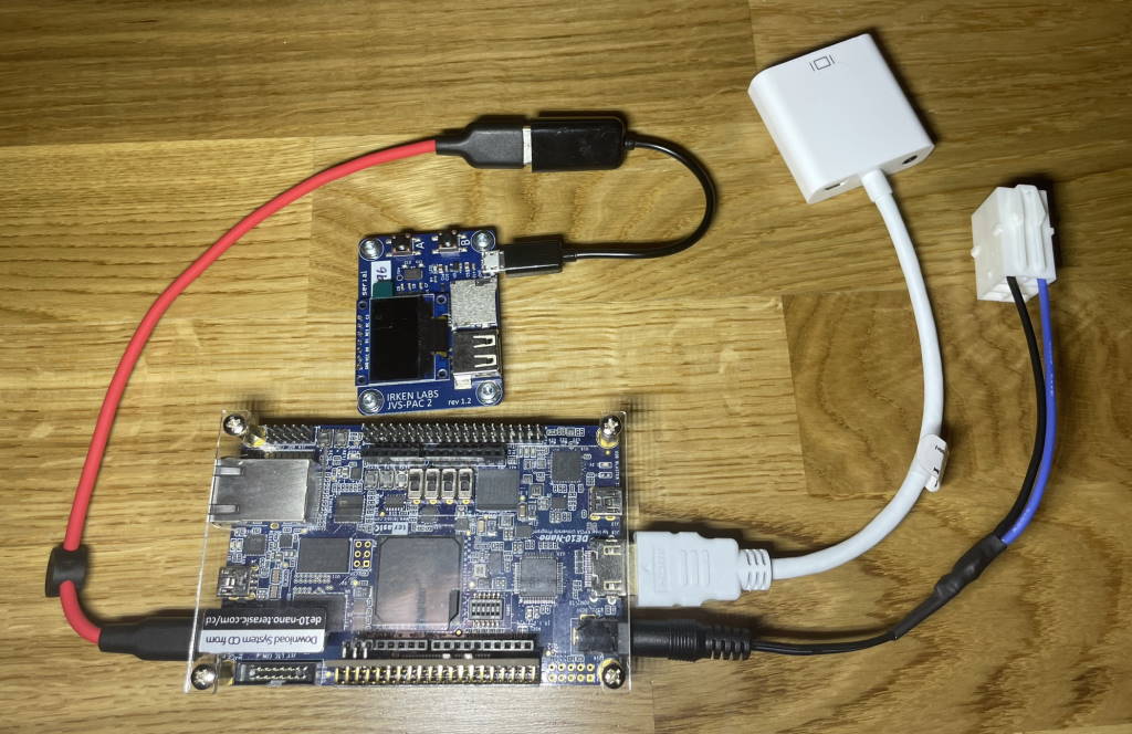
Step 2 – Hardware installation
This is pretty straight forward, plop the RAM module in place if you haven’t already and just connect everything together.
Power
DE10 power should be sourced from the same source as your cabinets DC power supply, or better yet – use your cabinets DC supply directly.
The HDMI to VGA dongle should work without any external supply, the one I got works just fine without connecting an external power supply.
Audio & Video
Both Audio & Video will go through the HDMI dongle, use the 3.5mm to RCA adapter for audio.
Controls
Use a USB OTG adapter between the DE10-Nano and the JVS-PAC 2. The JVS-PAC 2 has a specific shift mode for mister that lets you switches cores and change settings without using a separate keyboard.
Part 3 – Details for the technically inclined
MiSTer input system (stuff doesn’t work..!)
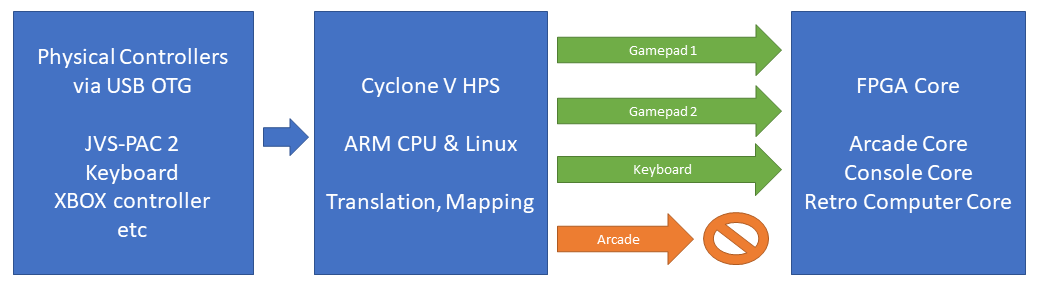
The input system of MiSTer is a bit of a mess when it comes to arcade cores. MiSTer cores can consume gamepad and/or keyboard input from the Linux subsystem, which makes sense from a console/retro-computer perspective, but no so much for arcade, where you have one cabinet. It’s not obvious where an arcade core should look for things like TEST, SERVICE, TILT etc, so naturally, it’s either not implemented or varies from core to core.
Gamepad input
For a console/computer core, one physical USB device will be player 1, another physical device can be player 2. This is all strongly tied to low-level USB workings, so input from one USB device is constrained to one player.
Since gamepads are not equal, you will also have to remap your gamepad. To complicate matters further, MiSTer can take input from a physical USB keyboard and present it to a core as ONE gamepad, not two.. There is a hack to get around this, but I will not get into that.
Keyboard
To avoid the complexities of the MiSTer input system, arcade cores can also consume keyboard input where there is no artificial player1/player2/cabinet limitations. Most cores support this, and most cores use the standard MAME mapping.
Getting out of trouble / limitations
If you for whatever reason used the “Define joystick buttons” of MiSTer and and pressed something on your cab – you now have a virtual gamepad, which will cause issues with things that consume keyboard input, like arcade cores.
To fix this, have a look in the “config/input” directory on the MiSTer SD card, and delete the .map files you have there.
Unfortunately a keyboard device like the JVS-PAC 2 can’t be both a “virtual gamepad” and a keyboard, unless you are super careful how you set up the mapping in MiSTer, so the JVS-PAC 2 is probably not a great option if you want to run retro-computers/consoles AND arcade cores in your cabinet – something you shouldn’t try in the first place, as it’s frowned upon by purists 🙂
In the absence of an arcade specific input system in MiSTer, I suspect MAME keyboard input will be the standard going forward.
If the particular core you want doesn’t support keyboard input or it uses strange keys, support the developer via Patreon and tell them you want standard MAME keyboard input.
Video output
In the early days of MiSTer, there was a need for analog RGB output. This was solved by making an open source “IO board” that connects to the 40 pin GPIO1 header on the DE10-nano, using 20 pins for video – 18 bits for RGB and 2 for sync. There are a couple of issues with this and the current implementation
- No video DAC, analog RGB is generated simply by using resistors on the GPIO signals, without an op-amp to ensure correct output impedance.
- No buffer on sync lines, it will be 3.3V instead of 5V – this is usually not an issue
- Although the datasheet for the DE10-nano states the GPIO 1 pins are protected, there is nothing in the schematic that reflects this
- As the number of available GPIO pins on the header is limited, you “only” get 18 bit RGB, i.e. 262k colors vs 16.7m with the HDMI dongle.
The first three points can be solved with better hardware on the IO board, but it’s not really needed as you have the direct_video option via HDMI.
HDMI and direct_video to RGB
The FPGA on the DE10-Nano has 24 pins routed to an ADV7513 HDMI transmitter. This is just a transmitter, it’s the FPGA’s job, i.e. the core, to make sure that what’s transmitted is HDMI compliant when it comes to resolutions and refresh rates. This fact is utilized with direct_video, where it violates HDMI resolutions and refresh rates and simply transmits core native video. Your HDMI flat panel monitor will not like this, but the HDMI-to-VGA dongle doesn’t care and will output a 24 bit RGB signal.
Apart from more colors and a proper video signal, the benefits of the dongle is they’re very cheap and do not risk damaging the FPGA due to mishaps when hooking up a monitor.
Audio output
The DE10-nano does not have a dedicated audio output, apart from digital audio via HDMI. The open source “IO board” provides analog audio utilizing an incredibly simple circuit consisting of 6 capacitors and 4 resistors, which is not known for stellar audio quality. The IO board also has the option of outputting TOSlink, that you can feed to an external audio DAC if you get a special 3.5mm cable or adapter.
Analog audio from HDMI
Utilizing a HDMI to VGA dongle as described above, it will extract the digital audio from the HDMI stream and convert it to analog using a DAC.
Last Updated on 2022-09-11 by admin