
Detailed mode of operation
Inputs
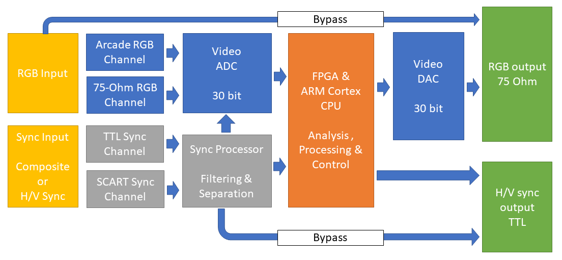
All input is via a single HD15-F connector, labeled “RGB INPUT”. It defaults to the “Arcade RGB” channel and the “TTL Sync” channel. This is the setting to use for Jamma games.
The 75-Ohm and Scart sync channel can be selected by editing the .ini file that will be created when you start the scaler with a micro-sd card inserted. Be aware that if your ‘scart system’ is modded, it may already output a sync signal that is compatible with the TTL channel, so try that first.
The TTL sync channel has an additional anti-jitter stage that is not present on the Scart sync channel.
Sync is forwarded to the sync processor which cleans the incoming sync, and separates it into H/V if the input signal is C-sync.
For RGB, the signal is terminated with either 75-ohm or 900-ohm depending on which channel is active, the Arcade channel also attenuates the signal.
From input to output
The system goes through different stages before it can output an image, the different stages are described below.
Stage 1
The system will be in stage 1 when no sync activity is detected. In stage 1, most of the circuitry is either off or in stand-by and the system consumes very little power. Once sync activity is detected, the FPGA is activated.
The scaler will illuminate the red LED while in stage 1.
Stage 1.5
If the sync is higher than about 24 kHz, the bypass function will be activated – this can be overridden in the .ini file. If sync is lost or goes below threshold, it will go back to stage 1.
Stage 2
The FPGA analyzes the signals from the sync processor, and once stable, move on to stage 3. If it fails to make sense of the incoming sync, it goes back to stage 1.
The scaler will blink the green LED while in stage 2.
Stage 3
ADC is powered up, and the FPGA analyses both sync and RGB from ADC. Individual analog gain for R,G & B will be adjusted to achieve maximum use of the ADC’s headroom while also ensuring proper white balance (RGB gain match).
If the output from the ADC is unstable, it will fall back to stage 2.
The scaler will blink the blue LED while in stage 3.
Stage 4
Analog pre-ADC gain is re-adjustet after 8 seconds, this interval can be changed in the .ini file. Video is line doubled, and the output section of the scaler is powered up.
To protect the ADC, gain will be re-adjusted in case there is clipping – i.e overload on the ADC input.
If sync is lost, it will revert back to stage 2.
If sync goes above scaling range, e.g. to 31kHz, it will quickly jump to stage 1.
The scaler will have red, green and blue LEDs illuminated while in stage 4.
Last Updated on 2022-09-11 by admin